
A material described as “conductive on both sides” may still have a high resistance between those sides. This distinction matters whenever charge must travel through a layered product rather than along one surface.
An electrical specification should identify the complete path being evaluated. Face conductivity, through-thickness conductivity, and connection resistance are separate questions.
Define the Current Path First
Three basic measurements can address different functions:
| Path | Main purpose |
|---|---|
| Along the front face | Evaluate conduction between locations on the working surface |
| Along the reverse face | Evaluate conduction across the backing or second functional face |
| Between front and reverse | Evaluate transfer through the assembled thickness |
A fourth useful path may run from a selected surface location to a connector, electrode, or grounding point.
Desco’s technical documentation distinguishes point-to-point, resistance-to-ground, and volume measurements, demonstrating why the measurement arrangement must be identified.[1]
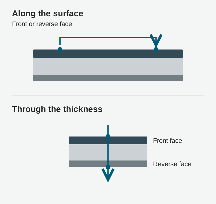
Why Two Conductive Faces May Be Isolated
Consider a hypothetical composite with conductive coatings on the front and back, separated by an insulating core or adhesive. Each face can support charge movement along itself while the separating layer restricts transfer between them.
Adding a connection that bridges the faces changes the electrical circuit. Without that connection, two low surface readings do not prove a low front-to-back resistance.
This is a consequence of the layer arrangement, so it should be checked on the actual supplied construction.
Interfaces Can Dominate the Result
A component may include several contacts: material to connector, coating to adhesive, conductive fabric to metal, or one flexible layer to another.
Contact area, pressure, surface condition, and mechanical movement can influence these interfaces. A well-performing face material can therefore produce an unsuitable assembled contact.
For development, test the component at its intended compression and compare it after unloading, bending, or cleaning where relevant. Record unstable readings rather than reporting only a favorable minimum.
Use Units That Match the Measurement
Resistance is reported in ohms. Surface resistivity is commonly expressed in ohms per square, while volume resistivity includes a length unit such as Ω·m or Ω·cm.
Resistivity and a measured resistance are not interchangeable quantities. Converting between them requires an appropriate geometry and assumptions about the specimen and current path.
For multilayer or nonuniform materials, a single apparent value may not reveal which layer or interface controls the result. Keep the raw measurement arrangement in the report.
Control the Test Setup
Specify the tested face, specimen support, electrode arrangement, contact force, voltage, read time, temperature, humidity, and conditioning.
Use a support that does not create an unintended parallel path for the measurement being made. Where the procedure requires guarding or another means of controlling leakage, follow the selected method rather than improvising with handheld probes.
Desco’s instructions also emphasize environmental conditions, electrode choice, and clean surfaces when interpreting electrical measurements.[1]
Test After Conversion
Lamination can introduce an insulating interface. Sewing can alter local contacts. A metal snap can connect one functional layer while failing to contact another.
Evaluate representative finished components with the intended adhesive, thread, connectors, and edge treatment. Check more than one location, especially near seams and the point farthest from a connection.
For ESD applications, the relevant surface must ultimately be integrated into the specified bonding or grounding arrangement; the broader system remains part of the assessment.[2]
Write a Path Based Specification
Replace “double-sided conductive leather” with separate requirements for each necessary path, including test conditions and acceptable variation.
Identify whether performance must remain acceptable during bending, under compression, or after defined aging. This makes the specification useful to the material supplier, product designer, and inspection team working on the same component.